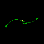
EVENT
EVENT objects are used to connect STATE objects to each other within a given MODE. They identify state transitions performed as a consequence of a specific event.The direction of the EVENT object indicates the direction of the state transition caused by the event.
EVENT objects must be connected at glue points on the STATE object. If there are not enough glue points on a STATE object add more useing the STATE objects add glue function.
Code Generation
The EVENT object has several properties associated with it which are used to guide the code generator during the code generation phase. These properties are accessed via the EVENT settings object dialog.These properties are:
- Event ID
- State Transition Function Name
Simulation Details
When the state machine dispatcher detects that an event has occured that exactly matches the event described by this EVENT object, it invokes the state transition function nominated by this EVENT object. The event described by this EVENT object is dependent on the CPU, MODE, current STATE (of the MODE) and event ID. Most of the information provided by the designer is represented graphically in the diagram, so there is no need for the designer to produce a cryptic table containing all this information. Producing such a table is one of the code generators jobs.Adding EVENT Objects To A Design
Normally the EVENT object is copied from the template window to the drawing window or from an existing EVENT object already on the drawing window. It must form part of a MODE (state machine) if code is to be generated for it. This is done by placing it within the perimitor of a MODE object and using the EVENT objects add to group function or gather function to tie it to the MODE.Related Information
MODE objects
STATE objects
INPUT objects
VCLK objects