PORTS
All input and output on the PIC is performed via the I/O ports. I/O ports are like RAM locations with wires leading from the bits to the pins of the microchip.I/O ports on a PIC are memory mapped. This means that to read from or write to a port on a PIC the program must read from or write to a special RAM location. To access PORTA on the 16F84, 16F628, 16F88, 16F876 or 16F877 the program must access the RAM at address location 5.
The I/O ports on the PIC can be used as either inputs or outputs. In order to use a port as an input it must be configured as an input. To use it as an output it must be configured as an output. Configuring a port for input or output is done by setting or clearing the data direction register for the port. On the PIC each bit of each port has a data direction bit. Therefore it is possible to set some bits within a port as inputs and others within the same port as outputs. The data direction bits can be thought of as flags that mark the direction in which the data moves between the outside world and the PIC (into the PIC or out of the PIC). A data direction register on the PIC is called a TRIS register. PORTA has a corresponding TRIS register called TRISA. PORTB has a corresponding TRIS register called TRISB.
e.g.
PORTA 0 0 0 0 0 0 0 0 TRISA 0 0 1 0 0 1 0 1 DIRECTION OUT OUT IN OUT OUT IN OUT IN To access TRISA on the 16F84, 16F628, 16F88, 16F876 or 16F877 the program must access the RAM at address location 133 (this is actually 5 + 128).
In XCSB, the ports and data direction registers are refered to by name not by address (although they can also be accessed directly by address).
Translating port bits to physical pin numbers
To identify which bit within which port is responsible for driving a particular PIC pin, look at the pin diagram for the PIC you are using. Locate the pin you are interested in and read off the label.The label will be of the form Rxj
where x will be A for PORTA, B for PORTB etc., and j will be the bit number within the port (in the range 0 to 7)
Using the bit within byte numbering scheme, each bit within PORTA is refered to as:
Microchip refers to PORTA bits as RA bits so PORTA5 becomes RA5
PORTA = PORTA7 PORTA6 PORTA5 PORTA4 PORTA3 PORTA2 PORTA1 PORTA0 For the 16F84, bits within PORTA and PORTB translate to the following pins
PORTA RA7 RA6 RA5 RA4 RA3 RA2 RA1 RA0 PIN N/C N/C N/C 3 2 1 18 17 PORTB RB7 RB6 RB5 RB4 RB3 RB2 RB1 RB0 PIN 13 12 11 10 9 8 7 6 NOTE: on the 16F84 bits 5, 6 and 7 of PORTA do not connect to any pins so they are shown as not connected or N/C

12f683 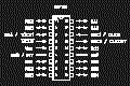
16F84 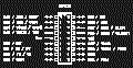
16F628 
16F688 
16F872
16F873
16F876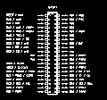
16f874
16f877
16f88
Writing to I/O pins
When the user writes a value to a port, all 8 bits are modified at the same time. However only the bits configured as outputs make it to the outside world.
If the intension is to turn a single pin on or off the user must be aware that writing a value to the port will cause all outputs to change, not just the one the user is interested in.
To set a specific bit (or patern of bits) within a port, the user should OR a 1 into that bit (or patern of bits)
e.g.
	// set PORTA bit 5 to output
	TRISA = TRISA & 0xDF

	// set PORTA bit 5 -- DETAILED EXPLANATION
	PORTA = PORTA | 0x20
To clear a specific bit (or patern of bits) within a port, the user should AND a 0 into that bit (or patern of bits)
e.g.
	// set PORTA bit 5 to output
	TRISA = TRISA & 0xDF

	// clear PORTA bit 5 -- DETAILED EXPLANATION
	PORTA = PORTA & 0xDF
An alternate method for setting and clearing pins is to use bit numberse.g.
	// set PORTA bit 5 to output
	TRISA = TRISA & ~(1 << 5)

	// set PORTA bit 5
	PORTA = PORTA | (1 << 5)

	// clear PORTA bit 5
	PORTA = PORTA & ~(1 << 5)
The expression (1 << 5) may look more complicated that the equivalent mask 0x20, however XCSB will generate the same efficient code for both.
Reading from I/O pins
When the user reads from the port, all 8 bits are read simultaniously. To read the value of a single bit the user should mask the required bit and look for 0 or NOT 0.e.g.
	// set PORTA bit 5 to input
	TRISA = TRISA | 0x20

	if (PORTA & 0x20) == 0 then
		// portA bit 5 is 0
	endif

	if (PORTA & 0x20) != 0 then
		// portA bit 5 is 1
	endif
An alternate method of checking pins is to use bit numberse.g.
	// set PORTA bit 5 to input
	TRISA = TRISA | (1 << 5)

	if (PORTA & (1 << 5)) == 0 then
		// portA bit 5 is 0
	endif

	if (PORTA & (1 << 5)) != 0 then
		// portA bit 5 is 1
	endif
The expression (1 << 5) may look more complicated that the equivalent mask 0x20, however XCSB will generate the same efficient code for both.Sometimes the value of an imput needs to be stored instead of acted upon immediately. This can be done in one of two ways
Method 1
- read the input into a variable, mask out the bit (only keep the bit that is of interest) and use the variable only in logical expressions
- read the input into a vaiable as the integer value 0 or 1
	// set PORTA bit 5 as input
	TRISA = TRISA | 0x20

	// read PORTA into temp and discard all bits except bit 5
	// temp will only be set to 0 or 0x20
	temp = PORTA & 0x20
NOTE: in XCSB zero represents FALSE and non-zero represents TRUEMethod 1 - using bit numbers// set PORTA bit 5 as input TRISA = TRISA | (1 << 5) // read PORTA into temp and discard all bits except bit 5 // temp will only be set to 0 or 0x20 temp = PORTA & (1 << 5)Method 2// set PORTA bit 5 as input TRISA = TRISA | 0x20 // set temp to 1 if PORTA bit 5 is 1 otherwise set temp to 0 temp = ((PORTA & 0x20) != 0)Method 2 - using bit numbers// set PORTA bit 5 as input TRISA = TRISA | (1 << 5) // set temp to 1 if PORTA bit 5 is 1 otherwise set temp to 0 temp = ((PORTA & (1 << 5)) != 0)NOTE: the statement "temp = ((PORTA & (1 << 5)) != 0)" looks complicated but is compiled into just 4 native PIC instructions. To put this into perpective, a 4MHz PIC could execute this statement 200,000 in 1 second