|
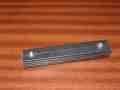
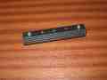
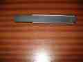
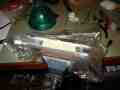
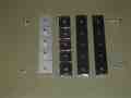
cut 4 lengths of steel bar
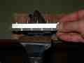
scribe a dividing line through the centre of 1 bar (this will be the top bar)
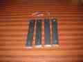
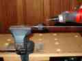
align the bars and clamp firmly at one end
drill a hole through all 4 bars at the other end (through the centre line)
secure the 4 bars together with a machine screw through the hole
drill a hole at the other end (again through all 4 bars)
|

|
|
|
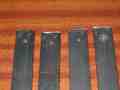
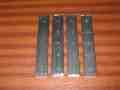
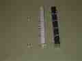
sperate the bars being careful to lay them in order so that the bundle
can be reassebled in the exact same order
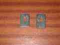
mark each bar so that its position in the bundle is indicated (the first
bar is marked with I, the second with II, the third with III and the
fourth with IIII. Be careful to mark the bars so the ends of the bars
are keyed.
|
|
|
|
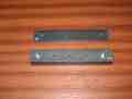
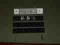
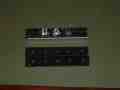
Assemble the first three bars into a stack. DO NOT include the fourth
bar. Ensure that the bars are in the correct order (I, II and III).
Secure the stack with a machine screw at eaxh end. The screws should be
tightend so that the individual bars cannot move within the stack and
the stack feels solid.
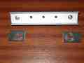
scribe a line half way along the top bar across the width of the bar
scribe 2 other lines (one on either side of the half way line) about
25mm apart.
Drill holes through the stack (all three bars) where the lines
intersect. It is very important that the holes are drilled vertical to
the stack.
|
|
|
|
|
|
|
|
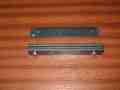
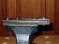
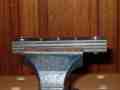
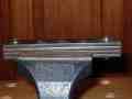
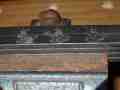
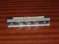
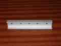
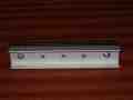
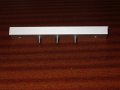
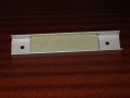
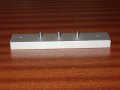
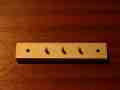
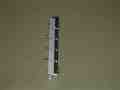
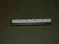
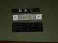
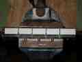
Assemble the stack using all 4 bars (in order)

This gives a template with 3 wells
|
|
The bearing pins are made from silver steel rod 4mm in diameter. The rod
is made to a high tolerance and is suitable for use as a bearing. Try
not to damage the surface of the rod while making the pins. Part of the
pin will be embedded in the bearing bracket and buried in epoxy putty.
This part of the pin can be damaged without ill effect.
Cut pin blanks at least 3mm longer that required
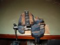
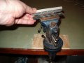
Mount a pin vice in a bench vice (the pin vice looks like a drill chuck>
Mount the silver steel rod in the pin vice. The entire length of the pin
being cut will probably fit inside the jaws of the pin vice so try to
clamp the steel rod near to the point where it will be cut (rather than
half way along the pin being made. This will limit the damage caused by
the jaws to a point where it does not mater.
|
|
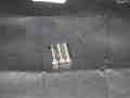
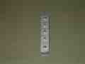
mount 3 pin blanks in the template (one in each well).

It may be necessary to release the screws at each end of the template in
order to get the pin blanks to slide into place. Ensure that the screws
are tightend once the pin blanks are sitting correctly in the wells. The
bars that make up the template should not be able to move.

secure the pin template in a bench vice. Do NOT adjust the template
screws while it is clamped in the vice. If you find that the bars in the
template move when you tighten the bench vice, you must remove the
template slacken off the screws, remove and reinsert the pin blanks and
THEN tighten the screws. Do not try to take short cuts here or you could
end up with bearings that will NOT turn freely.
|

|
grind or file the pin blanks down so that the top of each is level. The
top of each pin must be level, we do not need to make all the pins the
same hight at this stage. Do NOT grind the blanks down all the way to
the template, leave at least 1mm or 2mm sticking proud. This is to allow
the bottom to be ground cleanly as well.
|
|
|
|
remove each pin and re-insert it UPSIDE DOWN

Grind the pins down flush to the template
|
|
|
|
Remove and clean the pins. Use a solvent such as acetone. Do not use an
abrasive such as steel wool, emery paper or scouring powder. The silver
steel rod has a smooth finish which you want to take advantage of.

When I made my pins I found that the grinding process left a black
residue on the pins. This came from the template.
|
|
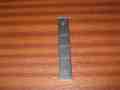
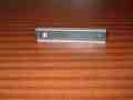
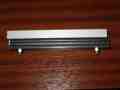
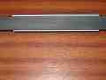
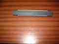
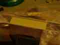
Cut a length of entruded aluminium so that it about the same length as
the template.
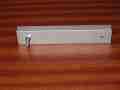
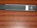
Clamp the top bar (bar I) of the template at one end to the inside of
the aluminium blank. Drill a hole through the other end using the
existing hole in the template as a guide.
Secure the template bar to the aluminium blank through the new hole
using a machine screw.
|

|
|

|
|

|
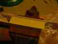
Remove the clamp

Drill a hole through the other end of the aluminium blank using the hole
in the template as a guide
|
|
|
|
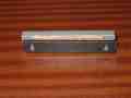
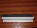
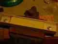
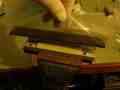
Assemble the top and bottom bars of the template around the aluminium
blank. The top bar (I) sits inside the blank and the bottom bar (IIII)
sits under the aluminium blank. A small piece of wood is placed between
the bottom bar and the aluminium blank.

The resulting work piece is held together with two machine screws (one
at each end).

BEWARE: The orientation of the bars and the aluminium blank is
important. If the screws do not slide into place easily then it is
probably assembled incorrectly.
|
|
|

|
|
|
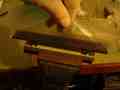
Drill three holes into the aluminium blank using the holes in the
template as a guide.

NOTE: It is very important that these holes are vertical. If you place
your work piece on a support (to overcome the protruding machine screws)
ensure that the result is level and will not affect the orientation of
the holes (THEY MUST BE VERTICAL HOLES).
|
|
|
|
|
|
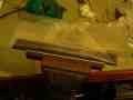
assemble the aluminium blank and the template bars (I, II and IIII, not
III). The template bars should be under the aluminium blank and all
should be secured using two machine screws (one at each end).

The pins should be located through the aluminium blank and sit in the
template wells. All the pins should touch the bottom template bar (IIII)
and should apear to protrude from the aluminium by the same amount.

NOTE: the pins should slide into place easily, if they do not it may be
necessary to slacken the screws, remove and re-insert the pins, then
tighten the screws again

BEWARE if the pins do not slide into place easily when the screws are
slack, this may indicate that the work piece has been assembled
incorrectly (perhaps the aluminium blank is backwards). Correct this
before going further.

NOTE: the inside of the aluminium blank should be thourughly cleaned and
degreased before it is assembled. The pins should also be degreased
before assembly. The cleaned parts should NOT be touched with bare
fingers during assembly or adjustment. Doing so will interfere with the
bonding of the epoxy putty and will result in very poor bearings.
|
|
|
|
|

|
|
|
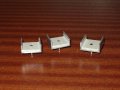
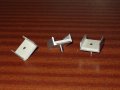
You will need to make 2 template inserts. These behave as damns and
level guides while the bearings are being built.

The inserts are made from the same bars as the template and have a hole
drilled into them to allow them to fit (loosely) around the machine
screws used to hold the  work piece together. The holes do not need to
be drilled accurately. Using a drill bit that is much bigger than the
machine screw head is ok. Just be careful not to make the hole too big
or the insert will be free to move about too much.
|
|
|

|
|

|
Cut another section of bar that is much longer that the template. This
bar should be from the same stock as the template bars. This bar will be
used to force the epoxy putty into the work piece and it must be long
enough to slide along the work piece without coming off the template
inserts (the damn walls).
|
|
|
|
|
|
|
|
|

|
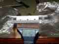
mount the work piece in a bench vice

wrap one template insert in thin polythene sheat (one layer of sheet
only) and place this over the machine screw. The polythene sheet acts as
a barrier between the template insert and the rest of the work piece.
Most importantly it acts as a barrier between the template insert and
the epoxy putty when it is added to the work piece. This allows the
template insert to be easily removed once the well has been filled with
epoxy putty without distrubing the putty.

do the same with the other template insert at the other end of the work
piece
|

|
|
|
|
|
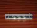
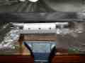
arrange the polythene sheet and template inserts to reveal a well in the
work piece
|
|
|
|
|
|
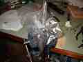
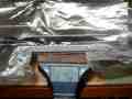
Mix a suitable quantity of expoy putty and fill the well (if in doubt
mix more than you think will be required since it will be easier to
discard excess putty than mix more once you have started filling the
well)
Wrap the slider in thin polythene sheet (one layer only) and place this
on top of the well so that it sits on the template inserts. Again the
polythene sheet will act as a barrier between the epoxy putty and the
slider. Ensure that this piece of polythene sheet is long enough to
allow the slider to travel across the work piece without gathering as it
travels back and fore.
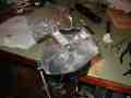
Work the slider from side to side while pressing down hard. This will
force the epoxy putty into the work piece and ensure good contact
between the putty and all exposed surfaces (including the pins)
|
|
|
|
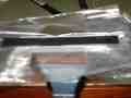
remove the slider and inspect the epoxy putty. If it does not come upto
the level of the template inserts, you need to add more. If there is too
much, do not worry, this will be trimmed away later.
|
|
|

|
Once you are happy that you have filled the well completely and evenly, carefully
remove the sliders polythene sheet.

NOTE with the sliders polythene sheet in place it is possible to remove
and replace the slider many times without damaging the epoxy putty in
the well, without the sheet the putty will stick to the slider and cause
many problems. So only remove the sheet when you have finished with the
slider.
|
|
|
|
carefully remove the template inserts, then slowly peel away the
protective polythene sheet.
|
|
If the epoxy putty is too high you can carefully push it down using the
slider (again protected by polythene sheet) WITHOUT the template inserts
(damns) in place.

This will cause the putty to spread along the work piece and you need to
be very carefull not to push putty onto the machine screws.

NOTE: the machine screws will interfere with this extra step and may
cause the polythene sheet to rip.

You do not need to perform this step since you will be trimming the set
putty down later with a file anyway.
|
|
|
|
|
|
Allow the epoxy putty to set hard and then remove the work piece from
the template
|

|
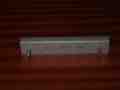
If all is well the work piece will easily stand on the pins. If it does
not or is very unstable you need to identify why and make a new work
piece with the defect corrected. If the fault is not easily corrected
and you need to make a new template then MAKE A NEW TEMPLATE. You will
need to make many bearings and they all need to be made with very
similar geometries. Working with a bad template that causes you to
rework all the finished bearings will cause you to waste much more time
than it would take to make a new template and WILL CAUSE YOU MANY
PROBLEMS later on.
|
|
|
|
|
|
The level of the epoxy putty in the work piece now needs to be reduced
so that it is at the same level as the tops of the pins. This is done by
carefully filing (by hand) the top off the epoxy putty to expose the
tops of the pins.
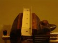
First secure the top bar (bar I) of the template in a bench vice such
that it is level and the top protrudes a little above the jaws of the
vice.
|
|
seat the work piece in the template bar such that the 3 pins sit in the
3 holes which were used to make them. Make sure the work piece is
oriented correctly with the template bar.

BEWARE: do NOT force the parts together as this could damage the
bearings. The 3 pins should slide in easily, if they do not you have
probably inserted the work piece backward.
|
|
|
|
|
|
|
|
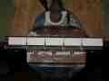
Useing a hand file, carefully file along the length of the epoxy putty
until the tops of the pins are exposed. This may take a while but it is
important to do this carefully keeping the surface level as you go. Do
NOT take off too much on one side thinking that you can even it up later
as you may spoil the bearings.

NOTE: you are makeing 3 bearing at a time here so even if this takes you
15 minutes it is still only 5 minutes per bearing.

WARNING: do NOT use an electric hand drill with grinding attachment at
this stage unless you are VERY confident about your skill.
|

|
|
|
|
|
|
|
|

|
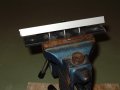
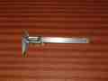
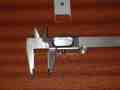
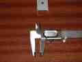
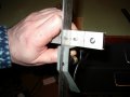
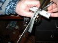
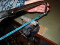
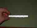
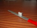
Using a caliper, measure the actual distance between the pins.

Shown here is a vernier caliper. This particular type of caliper allows
you to read off fractions of a millimeter. This level of accuracy is not
needed for this stage however the gage on this tool makes it more
convenient to work with than an ordinary caliper.
|
|
|
|
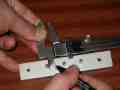
Half the distance
|
|
Mark the mid point between the pins
|
|
|
|
|
|
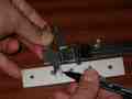
Using the same measurement mark a point before the first pin and after
the last pin. The distance between the holes and the pins is not
important since the holes are on metal that will be discared.
|
|
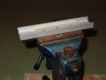
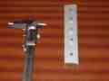
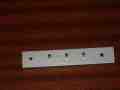
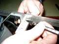
Using a square and the marks already made, draw lines dividing the work
piece. It is important that these divisions are square to the edge of
the work piece. Holding the square as shown will produce an accurate
guide for the lines.
|
|
|
|
|
|
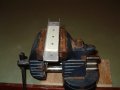
Secure the work piece upside down on the template bars I, II and III using machine
screws. The pins will be pointing away from the template and NOT into the template.

NOTE: the orientation of bars I, II and III should be the same as when the template
was made.
|
|
|
|
|
|
|
|
Secure the work piece in a bench vice such that the jaws grip the
template and NOT the aluminium blank.

The work piece should be level as this will help you cut vertically.

NOTE: by opening the jaws of the vice such that they are just slightly
wider than the template but not as wide as the aluminium blank, it is
simply a mater of sitting the work piece in the vice and lightly
tightening the jaws. This will help level the work piece with minimum
effort.
|
|
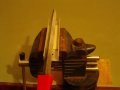
Cut along the lines by hand using a hack saw. This is very easy and does
not require much effort. Do not use a hand drill and cutting disc for
this task.

Cut through until you meet the steel of the template. You will know when
this happens (providing you are not rushing) because the cut will feel
different. Try to cut evenly and level (across the top not at an angle
to it).

BEWARE: as you are cutting down the blade may be angled sideways. Try to
keep the blade vertical and produce a vertical cut (straight down).
|

|
|
|
NOTE: the cuts are not complete
|
|
Disassemble the aluminium blank and template.
|
|
Re-assemble the aluminium blank and template such that bar I is moved to
the other side of the aluminium blank. The pins should now fit into bar I.

NOTE: do NOT use screws to hold the work piece together. The work piece
should be held together using your fingers until it is secured into a
bench vice.
|
|
|
|
|
|
lightly secure the work piece in a bench vice with the side at the top.

NOTE: use the jaws of the vice to grip the work piece just below the
pins. It is important that you leave a small gap between the pins and the
vice jaw otherwise you could damage the bearing when you tighten the
vice.
|
|
Complete the cuts through the side of the aluminium blank

Repeat the process for the other side of the work piece
|
|
it is likely that not all the aluminium and epoxy has been completely
cut through. Exerting a light force should easily seperate the bearing.

clean (tidy) the ends of each bearing using a hand file.
|
|
It should now be possible to stand each bearing on the end of its pin
with very little effort. If you find this is very difficult or the
bearing is very unstable you need to identify why and make new bearings
with the defect corrected. If the fault is not easily corrected and you
need to make a new template then MAKE A NEW TEMPLATE. You will need to
make many bearings and they all need to be made with very similar
geometries. Working with a bad template that causes you to rework all
the finished bearings will cause you to waste much more time than it
would take to make a new template and WILL CAUSE YOU MANY PROBLEMS later
on.
|
|
|


